Engine Upgrade.
It’s about time that I put pen to paper or is it hammering the keyboard?
I was intrigued by the presentation at our club night (Mini Car Club of Auckland), some time ago, from Mark Stokes on how to go about legally modifying your Mini. Exotic engines were mentioned etc. etc.
But that was not for me. In the late nineties I had spent mega bucks on the 1330 I had in my Mini to bring it up to around 85bhp. But then, after about a ten year trashing, there was this o so faint noise from the front of the car that, over time, was getting worse and worse. Oil pressure was still good (60psi), power didn’t seem to have diminished so, what’s going on? I decided to ignore it and carry on as per normal. The daily short runs to and from work were most certainly not helping. And then the gearbox starting to get a bit temperamental. Shifting between first and second was getting a bit difficult when cold and it sounded that the synchros were on the way out.
All
in all it looked like I was facing a
total engine/gearbox replacement or repair and I didn’t
wanted to get a lesser
of an engine. And then I saw Rex’s Mini with the
Just by sheer luck I found a Suzuki Swift GTI race car that the owner was about to replace with a late model Suzuki. I bought the car for $1500, took the engine, wire lume and ECU out of the car and through away the car. Actually, I kept the dash and the lights too and the 14” alloy wheels. You never know what it is good for… The wheels are now sold which knocked off a few buck of the purchase price.
And then I needed some steel to make up a new sub-frame. Well, what’d you know? Working at the steel mill has it advantages. I can buy 1.5t of steel a year for cheap. Okay, I didn’t need that much but I bought a couple of lengths of box section and got that dropped off at home.
Where did I had that spare front sub-frame? Ah, behind the shed, I found it.
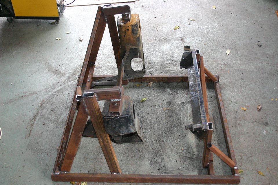
Now how can I chop up the sub-frame and still retaining the mount points? You build a jig around it like this:
And
then the angle grinder came out. As you
know, the Mini motor is cradled east/west but the Suzuki engine is
having its
engine mounts to the back and front. I had a pretty good idea how I
wanted the
sub-frame to end up after I got in touch with Philip
Smurthwaite in the
The first cut:
And then the second:
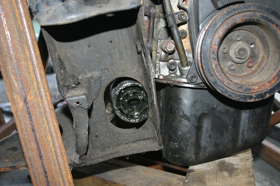
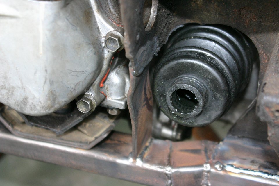
There was now space to have the Suzuki engine to hang in the hole and time to start designing the rest of the sub-frame. I did design it on the fly. Stitch a bit in and take it out if it didn’t look right or didn’t fit well. It was a slow process but a lot of fun to do. When I hung the engine for the first time in its expected location, a few issues showed up with the most striking problem the driveshaft location. I wasn’t able to put the engine far enough back to get the drive shafts through the space in the towers of the sub-frame.
It just means more work for the angle grinder. The diff casing was another small hurdle to overcome. The back side of the sub-frame needed just a little cut out to make space for it.
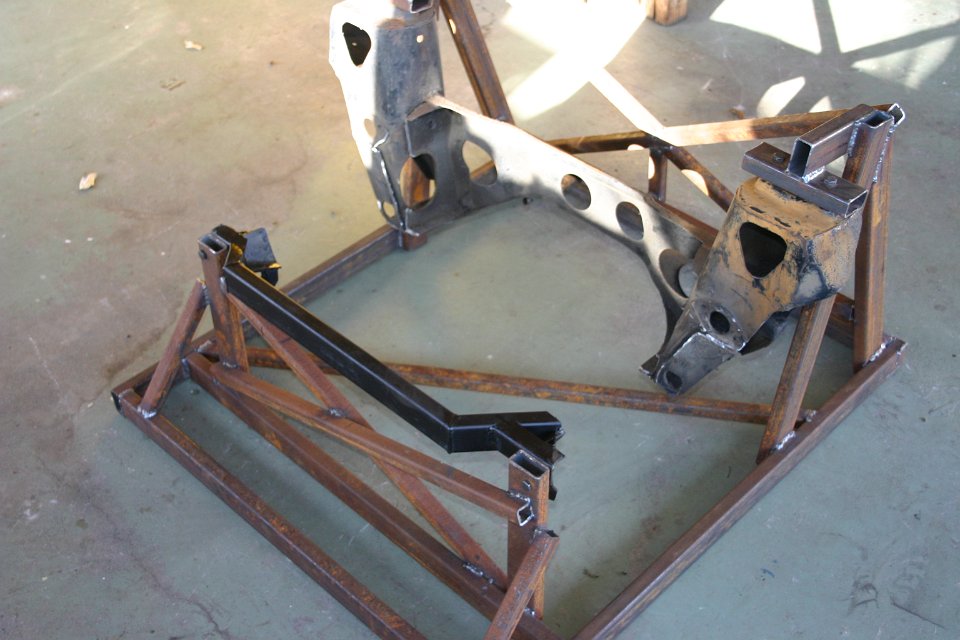
I ended up making a new support for the towers in the sub-frame to make enough space for the drive shafts like this:
This posed another problem. The mounting point of the pin for the bottom suspension arm was gone. I borrowed a spare bottom arm from Graham Crispe and made up a new mounting point like this:
I got new pins machined by a local engineering shop and they fitted like a glove.
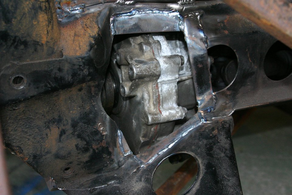
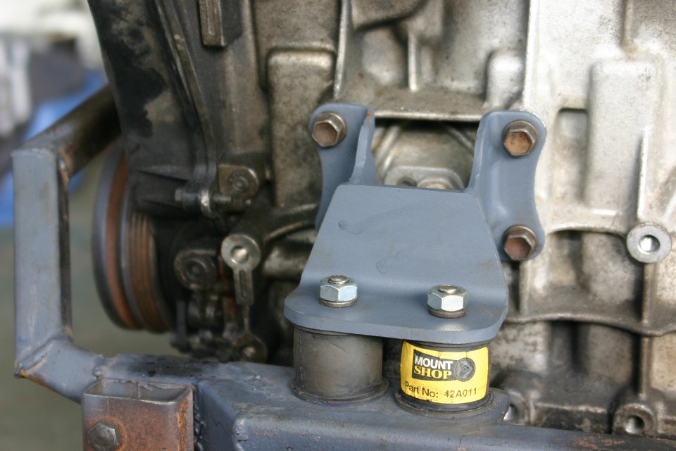
Next on the list were the engine mounts. Again all was designed on the fly. A couple of cuts of angle line, part of the old engine mount, a bit of welding and presto, new engine mounts. According to the specs of the rubbers, only one would have been sufficient but I thought better safe that sorry and fitted two on both the front and back of the engine.
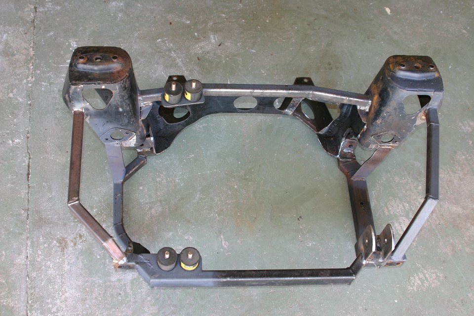
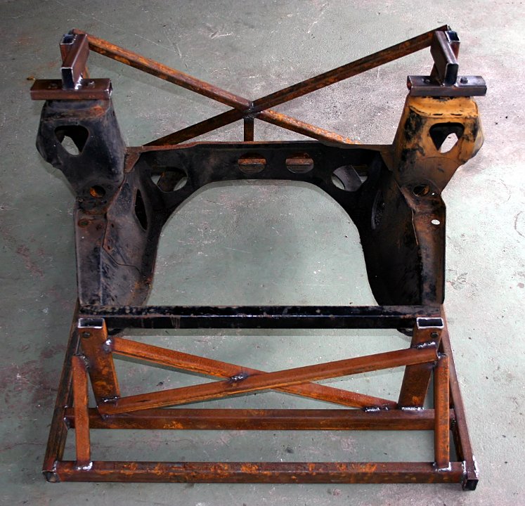
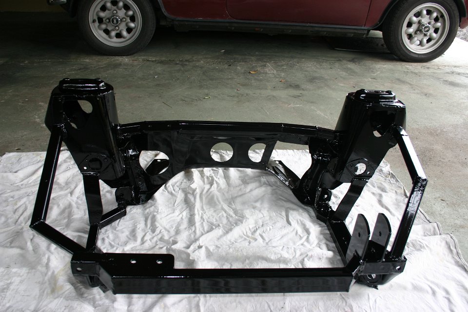
Talking to Mark Stokes he told me that he wanted to see my handy work before painting and with the welds untouched. This was imperative to assess the quality of the work. Another very good point Mark made was that getting in touch with him BEFORE you start a project like this is very important. He will guide you through the phases of what you can and can’t do. Don’t show up with a finished car and ask for a cert. That’s not how it’s working. All phases of the work need to be inspected before it is put together. This is what I showed to Mark:
And this is how it looked after sandblasting and painting:
Having the sub-frame finished, it was time to pay attention to the engine. I mean it was taken out of the Swift and used to make up the sub-frame but I needed it to go again too. I had bought the Swift mid 2007 so, it’s been sitting idle ever since. First a few basic things. The engine was an ex race engine and has been running on avgas only due to the very high compression. That needed changing. Secondly, the GTI was originally on 14” wheels and to accommodate this, the diff final drive ratio was 4.105:1. Get out the calculator and you will quickly find that on 12” wheels with this diff and in fifth gear the engine would do 4000rpm at 100km/h. That’s not very palatable to me. Now I knew that the Suzuki swift GL and the Holden Barina were on 12” wheels so finding a gearbox from one of those cars would easily fix my revving issue because the diff ratio for those cars was 3.523:1 which is much closer to the standard Mini diff ration of 3.44:1. With a quick look on TradeMe I found an Mk1 gearbox of a Suzuki GL for just $150. There is actually some significance to get a MK1 gearbox. Rumour has it that they are stronger than the later models MK2 and up.
Just get the calculator out will you and you will see that, with the GL gearbox, the engine would run at 3000rpm for 100km/h in fifth gear. Well done, just what the doctor ordered. Going the GL gearbox way mend I was sacrificing some of the acceleration in the higher gears but I didn’t see that as an issue. What’s the problem shifting down on or two gears?
Okay, the gearbox was sorted, now on to the engine.
The head needed some attention because of the high compression ratio so, off came the head and down to the head shop we went. I needed to know what the cc of the combustion chambers was, to work out a plan to reduce the compression. The standard GTI head has a 34cc combustion chamber and this head turned out to have 27cc!!!
And
there was another problem with the
head. The valve stems were bent. Whoever had been setting up this
engine for
racing completely messed it up. Machining so much of the head means
that you
have to adjust the
To get the c/r down to a more reasonable level I calculated that a 0.8mm decompression plate was needed. With the given bore, 0.8mm would add 4cc to the total combustion chamber and bringing the compression down to 10.5:1. I could have gone for two head gaskets stacked on top of each other but, with a compressed thickness of 1.4mm, it would bring the compression down to far and taking the fun out of the whole project.
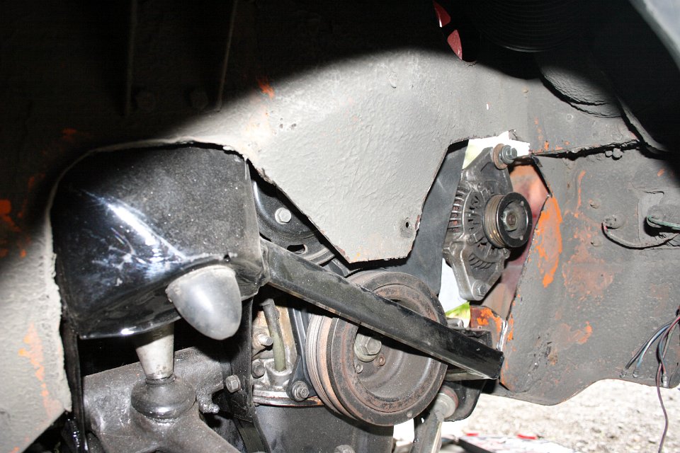
The next step was the exhaust manifold which was custom made to suit the space in the Mini. The alternator, which was originally on the back of the engine, was moved to the front of the engine on home grown brackets. This was temporarily fitted to make sure that the, to be designed exhaust manifold, stayed well clear of it.
It was now getting very close to park up my Mini and to drop out the engine and sub-frame. September 2008 was the big moment. The 1330 was dropped out and so was the sub-frame.
The new sub-frame fitted like a glove. Looks like the jig had done its job very well.
The next thing was to drop the engine in. Again, all seem to fit exceptionally well.
A small modification needed to be made on the driver’s side inner guard to accommodate the relocated alternator.
The cut could have been a bit smaller but never mind, what’s done is done…
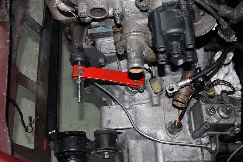
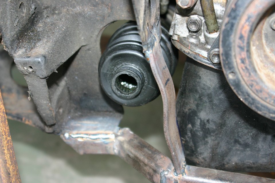
On the Suzuki, the clutch was cable operated but I didn’t see that as the best option.
If I had gone to the cable option, there would have been the necessity to change the paddle box with all the complications that I could do without so, I made the clutch hydraulic operated using the standard clutch master and slave cylinder. After some measurements I found that the stroke of the slave cylinder was nearly the same as the travel of the cable clutch. It was now just a matter of finding the right location for the slave cylinder. Rotating the clutch lever by 90deg and shortening it by 5mm I was able to make a working clutch with the slave cylinder fitted to the front of the engine.
Next on the list was getting some fuel to the engine. Being a fuel injected engine I needed two fuel lines. One for the feed and one as a return.
Also,
with the GTI engine more powerful, a
larger fuel line was required and the old line would just fine as a
return.
Feeding this engine I got myself a Holden Commodore external fuel pump
and
fitted that in the rear sub-frame.
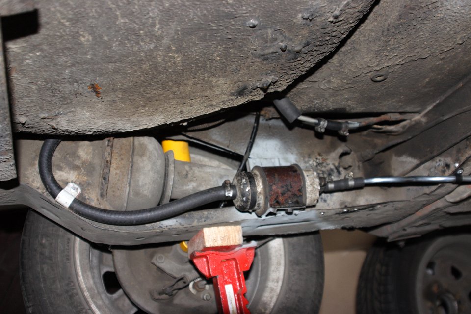
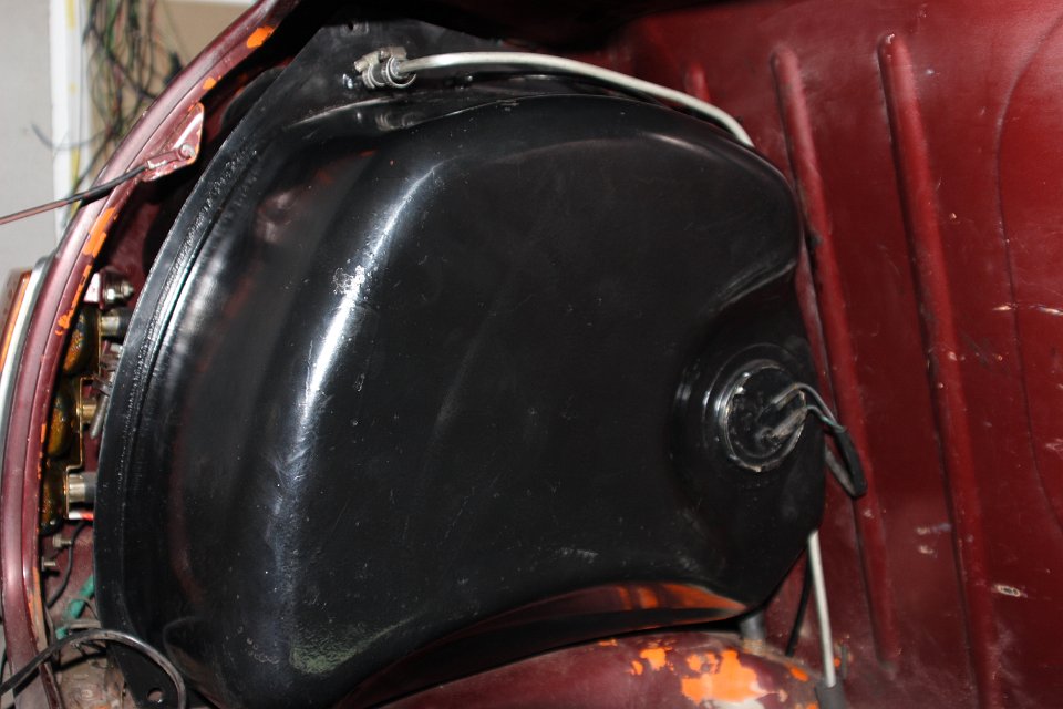
But
there was a problem with
the size of the tank connection of just 4mm id. The large fuel pump was
sucking fuel through a straw, cavitating badly and it distroyed itself.
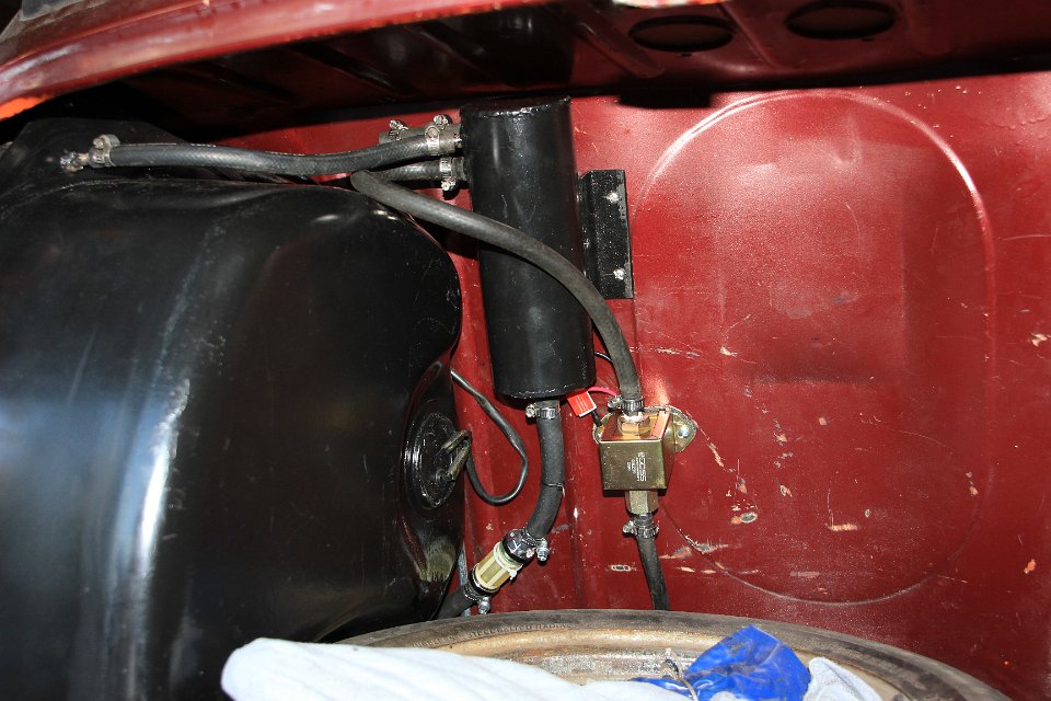
That problem was sorted with a surge tank wich was constantly topped up
with a normal facet pump. A large 12mm connection from the surge tank
to the new fuel pump was made and the return line from the motor was
also fed back in the surge tank. The overflow of the surge tank is now
going back to the tank. That sorted the fueling problem outright.
The engine electronics was a whole new ball game. I wanted to retain as much as possible of the old Mini wiring and fully integrating the GTI wiring. I unravelled the GTI wire lume and, with the help of a copy of the GTI factory manual, I managed to fully integrate the GTI into the Mini. All Mini gauges and lights were connected trough the GTI lume. The only sensor on the engine that I had to replace was the water temp because the GTI one would not suite the Mini temperature gauge.
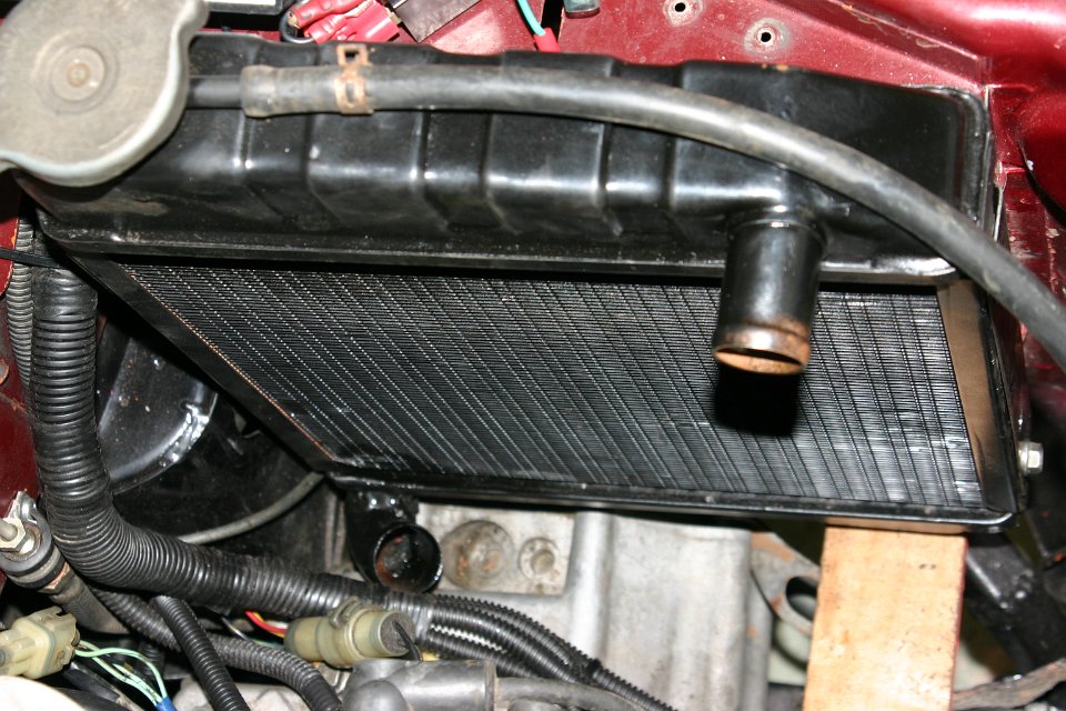
Next was the somewhat important cooling of the engine. I’d been to the radiator shop to see if I could make a custom radiator or perhaps do a re-core on the Suzuki radiator. But then I rang Lee from Mini Bits and he got me a brand new radiator which I subsequently dropped off at the radiator shop to get it modified to match my application. The overflow needed to come out the other way and the bottom outlet on the radiator needed modifying as you can see on this photo. I needed to point up for a bit.
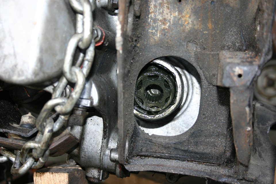
Just about after nearly completed the project I realised a couple of drive shafts wouldn’t go amiss. The spline on the Mini shaft looked the same as on the GTI shaft but after close inspection there was one grove difference. Okay, custom shafts then.
I measured up the distance between the CV joint face and the potjoint face plus half the travel of the potjoint CV and on both sides of the engine. There was less than one mm difference so it was pretty save to make both shafts the same length.
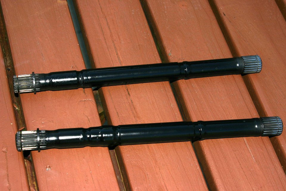
Off I went with two Mini and two Suzuki shafts to this most amazing engineering shop of Vaughn Walters just outside Waiuku. I explained to him what I wanted like cut them in half and budweld them together to make hybrid shafts and he said, no problem. A couple of days later I picked up new drive shafts and I was unable to see where the welding was done.
A fine pair of remanufactured drive shafts. One side Mini spline and the other side Suzuki. I painted them black.
Vaughn told me that, if the
engine could make 1000bhp, he would guaranty the welding up to 1000bhp.
I was mighty
impressed with his handy
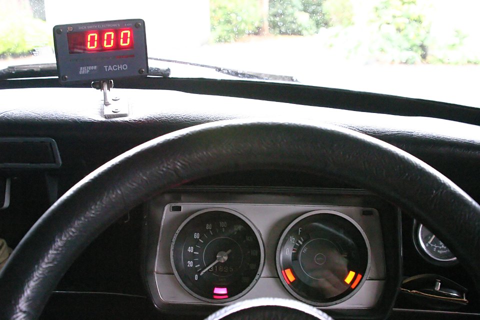
It was now getting very close to the scary part of the project. Firing up the engine for the first time. I had cold tested everything possible. That’s what you get with a fuel injected engine. The ECU will tell you of any fault with sensors and so on. But how could I see the ECU feedback? Well, there is this purple light on the dash below the speedo that was originally, and I mean really a long time ago, intended to wire up to the ‘oil filter blocked’ switch which is really not there anymore and probably never was there in first place. Now, that’s the light I’ve connected to the ECU for status feedback.
Oh, did I tell you that the Suzuki rods for
the gear stick were to long. Well, after fitting the Suzuki shifter I
just chopped and shortened the rods.
Anyway, I fired up the engine and it ran right away after just two turns of the starter. Magic.
Observed
all gauges, looked for smoke or
funny smells, but nothing so, it was time to go up and down the drive
for a
bit. Whow, she is going alright. Maybe I should go down the road for a
bit.
Maybe I should go around the block for a bit. Man did it feel good.
From here
on it’s been all excitement. I rang Mark Stokes and we
organised some time for
the certification process. Booked some space at the local garage and
when I
drove in and Mark got on with his business, the whole workshop stopped
to see
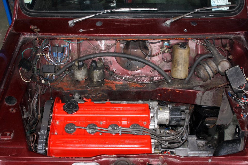
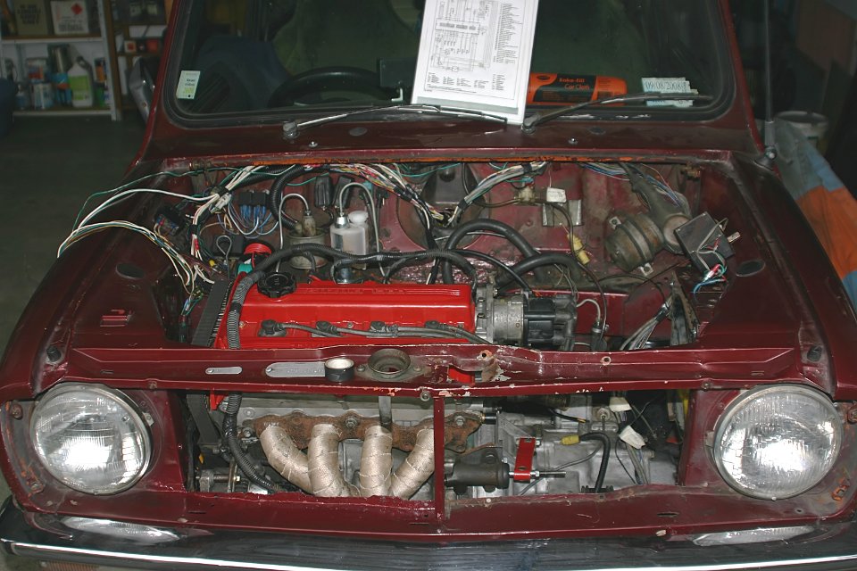
what I had under the bonnet. I never looked back. I know some Mini
owners might
frown upon exotic engines in a Mini but the way this engine fits is
just
perfect and it really looks like it could have been a factory fit.
Maybe, just
maybe if BMC or
The fuel economy is heaps better than the old engine and, if I want to, there is loads of power on tap. The standard GTI engine is good for 105bhp but with all the mods I’ve done to the engine it is estimated (not by me) that it’s probably close to 140bhp. This engine really starts to feel happy above the 5000rpm and happily revs to 8000rpm. That’s where the ECU stops it by turning off the ignition.
The mods done on the engine are: Cultus inlet manifold and injectors, high lift cam, extractors, large bore exhaust, free flow muffler and modified ECU. The 7200rpm fuel cut has been taken out and the fuelling is slightly changed.
The only disadvantage is that power only comes on above the 5000rpm. So what, there is still 3000rpm to go from there and boy does it feel good.